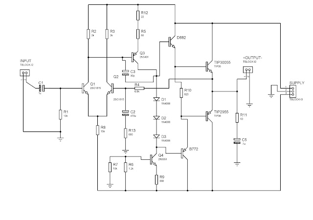
This is the schematic diagram of our amplifier:
This is basically a 40 W power amplifier.
NOTE:
SUPPLY:
The supply used for this is +24V and -24V 3A center tapped transformer. Then, the the transformer goes through a rectifier bridge which will convert the AC voltage of -24V and +24V to obtain a DC voltage of -35 V and +35 V output for the main circuit supply. A circuit is shown below for obtaining the 35V and -35V.
CAPACITOR V-Rating:
Also the capacitor voltage needed is 50V. It is normally recommended to give a good amount of room when choosing the voltage of the capacitor. Meaning, if you want a capacitor to hold 35 volts, don't choose exactly a 35 volt-rated capacitor. Leave some room for a safety margin just in case the power supply voltage ever increase due to any reasons in order to avoid explosion of the capacitor as it charges.
RESISTOR Wattage-Rating:
An ideal wattage of a resistor to be used for this circuit is a 1/2 or 1 watt resistor. The purpose of this is to emulate a pure resistance in a circuit and to avoid the resistor from burning up due to heat by resisting the current in a large amount of power.
COMMON GROUND:
Ensure your circuit to have all the grounds to be common, from AC to DC connections. All of the ground connection must be connected together to avoid "humming" sound from the speaker. A system grounded at two different points with a potential difference between the two grounds can cause unwanted noise voltage in the circuit paths. BE SURE TO CONNECT ALL GROUNDS INTO A SINGLE POINT GROUND.
HEAT SINK:
As for the transistors such as the "TIP3055"(i misspelled the number on the circuit) and the "TIP2955" it would need a huge heat sink since this two transistors are responsible form the amplification of the signal, therefore dissipating a lot of heat. As you can see on the images below in the inside of the case, there are two long metal rods place on the side, those are the heat sink for our transistors since it emits larger power amplification thus dissipating a lot of heat.
This is the schematic diagram of the power supply used in this Amplifier. Credits to Engr. Kendrick Villaruel and Engr. Ella Laguindam for providing this circuit.
In order to clearly understand and comprehend how the set-up works, here is a picture of how the amplifier is being assembled.
What happened in this diagram???
Well first of all, we bought a pre-amplifier from an electronics shop. The pre-amp is a ready made circuit in which it would be connected to the main amplifier circuit in order to perform an amplification from our amplifier. To make it short, the sounds from the pre-amp would be amplified by the main amplifier circuit. The pre-amp I bought was a 20 W amplifier. The 20 W will be amplified by the 40 W circuit to maximize the power from the main circuit. Then from the main amplifier, it directly goes out to the speakers and the tweeters. Be sure to check the specification of the component needed for this circuit.
NOTE:
TWEETER:
As for the tweeter, you would need a non-polarized capacitor with a value of 2.2uF/50V or higher, also known as capacitor "condenser". The capacitor in this circuit acts as a high pass filter, which means it will block low frequency component and let the high frequency component pass through. It will attenuate the low frequency.
12Volts:
You might wonder why there is a regulated 12VDC or an unregulated 12VDC located on the circuit. The 12VDC is used to power up the pre-amp. You can choose between the two either you make your own 12VDC or just purchase an adapter from an electronic shop with an ampere rating of 1.5A. But if you're transformer is 3A, it is much better to generate your own 12VDC for supplying the pre-amp.
Here are some pictures of the 40W amplifier construction.
Our casing design was made to be DOMO. DOMO was a famous cartoon character from our school during that time, so me and my partner decided to have our amplifier case to be DOMO. It was fun and exhausting making this amplifier. Fortunately, we were able to finish it up and showed off our amplifier during the engineering exhibit.
Here are some videos from our DOMO Amplifier.
Inside DOMO
Engineering Exhibit (DOMO)
DOMO AMPLIFIER MADE BY:
KIRK BENEDICT P. MACARAEG & JONALD B. SARMIENTO


No comments:
Post a Comment