Sorry
it took me a long time to post this, this is actually our thesis, The Fleet
management System. It composes of all the tutorial I made with GSM and GPS
modules. This is the summation of all the projects I made along with my thesis
partner Areo joseph Paolo Bartolome.
Introduction:
This
research basically focuses on the development of a system that monitors
vehicles in Mindanao area and its fuel consumption. More specifically, the system
will:
1. Secure
the Global Positioning System (GPS) device installed in the vehicle.
1.1
The driver cannot
disable and manipulate the GPS device.
1.2
The ignition of the
vehicle will be disabled if the F.M.S. device is removed improperly.
1.3
The registered owner
can enable and disable the GPS through the use of the GSM.
1.4
The registered owner
can disable the vehicle’s power through the system with a delay of 30 seconds.
1.5
The device will be
powered from the vehicle’s battery.
2. Transmit
information from its current location to the monitoring station. The device can
do the following:
2.1
Locates the vehicle’s
position within Mindanao area by the use of the GPS module.
2.2
Transmits data to the
monitoring station by the use of the GSM module.
2.3
Transmits security
status information of the vehicle.
2.4
Sends the collected
data in real-time.
3. Receive
the collected information from the transmitter to the monitoring station. The
device can do the following:
3.1
Receives the vehicle’s
location through the use of the GSM module.
3.2
Stores the received
data in a database.
3.3
Calculates the distance
travelled by the vehicle.
4. Secure
an access user code only for the registered owner.
4.1
Registered vehicle can
be monitored only by the registered owner.
4.2
Registered owner can
access the system through an internet connection.
4.3
Vehicle information will
be secured with a unique password for each of the registered owner.
5. Displays
the collected data in the system.
5.1
Vehicle’s location will
be displayed on an electronic map in line with Google Earth map.
5.2
Displays the
calculation of fuel consumption, travelled distance, and vehicle’s status.
5.3
Receive and stores the
data.
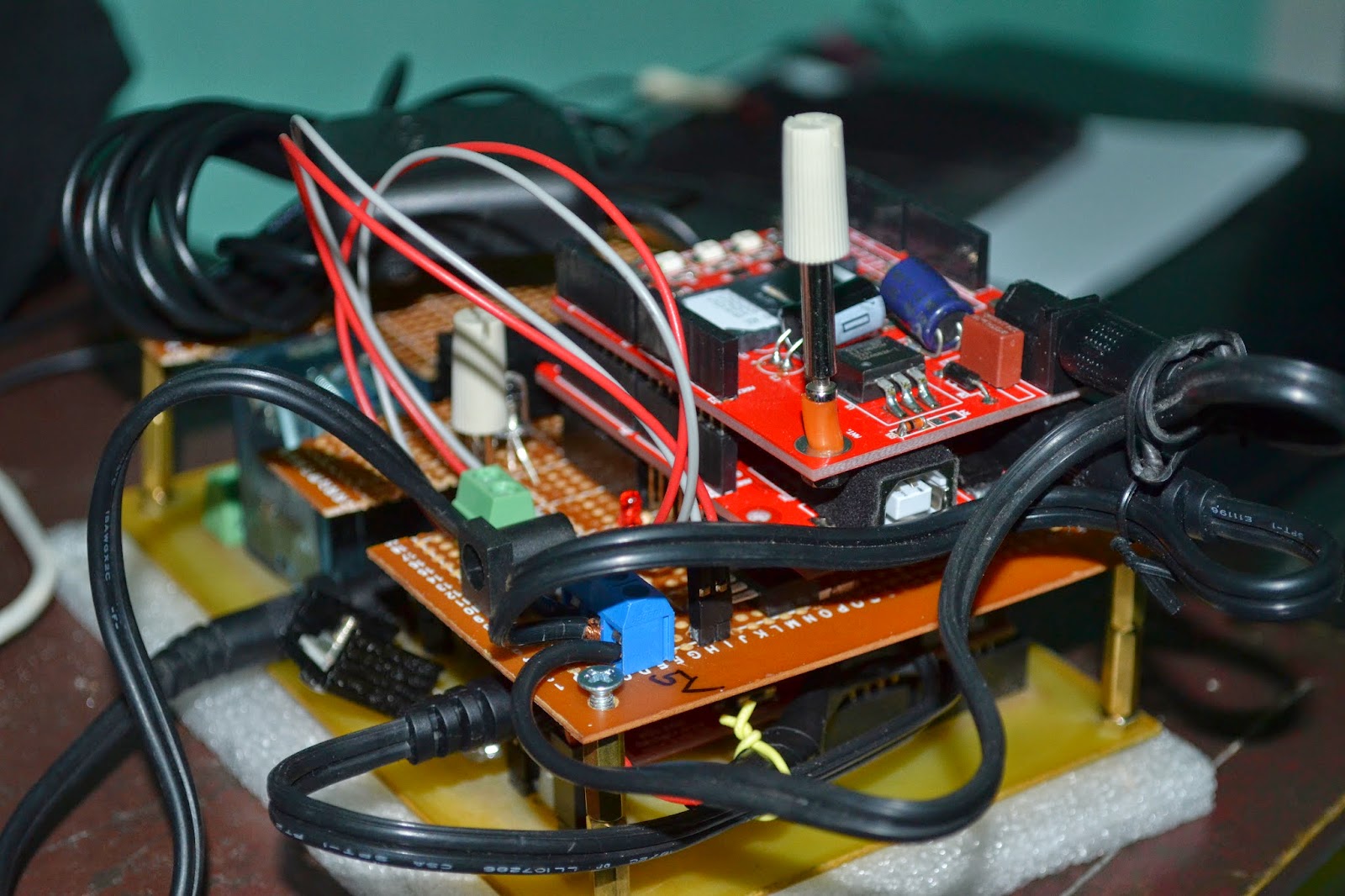
Circuit Image:


Fleet Management Video:


