Thursday 5 December 2013

GPS Shield with PIC16F877A

Hello there! Here is another integration test for my research proposal (Fleet Management System) that composes of a GPS Shield. In this project, I have integrated the GPS Shield with the PIC16F877A and a 2x16 LCD. The information from the GPS Satellite, specifically the latitude and the longitude, would be captured and will be displayed on the 2X16 LCD.

The image shown below is the GPS Shield module that I used for my project. You may be able to purchase this module at http://www.e-gizmo.com/KIT/gps%20shield.html for 1,385 pesos.


An image below that is shown is the circuit diagram for the connection of the devices which are the GPS Shield, the MCU PIC16F877A and lastly the 2x16 LCD.


As I said earlier, I used a "2x16" LCD and the image shown here is a"2x14" LCD. This is because i used proteus for circuit design and simulation and the 15 and 16 are neglected due to the built in function of the device. In actual, the pin 15 is the anode and the 16 is the cathode. The purpose of pin 15 and 16 is that it turns on the LED/light background of the LCD. To attain this, simply connect pin 15 of the LCD to the 5VDC source and the pin 16 to the GND.

As for the TX and RX connection, only connect the Rx of the GPS to the Rx of the PIC16F877A, We will neglect the TX since we would only retrieve the information of the latitude and longitude. 

Here is the program code I have made for this project:
NOTE: The programming software i used is the MikroC PIC Pro. In order for this to work, you need to download the MikroC PIC Pro and download the NMEA library function in order for you to be able to utilize some functions used for the GPS Shield. The NMEA library can be downloaded here : http://www.libstock.com/projects/view/695/nmea-library


/*---------------------------FLEET MANAGEMENT SYSTEM-------------------------
         MikroC Programming by Kirk
----------------------------------------------------------------------------*/

// LCD module connections
sbit LCD_RS at RB4_bit;
sbit LCD_EN at RB5_bit;
sbit LCD_D4 at RB0_bit;
sbit LCD_D5 at RB1_bit;
sbit LCD_D6 at RB2_bit;
sbit LCD_D7 at RB3_bit;

sbit LCD_RS_Direction at TRISB4_bit;
sbit LCD_EN_Direction at TRISB5_bit;
sbit LCD_D4_Direction at TRISB0_bit;
sbit LCD_D5_Direction at TRISB1_bit;
sbit LCD_D6_Direction at TRISB2_bit;
sbit LCD_D7_Direction at TRISB3_bit;
// End LCD module connections


char txt5[] = "GPS with PIC877A";
char txt6[] = "F.M.S.";


// Variables
int i = 0;
int received = 0;
char DataType[] = "GPXXX";
char NMEA[] = "$xxxxx,xxxxxxxxx,xxxx.xxx,x,xxxxx.xxx,x,x,xx,x.x,xxx.x,x,xx.x,x,,*xx";
char receive;
// End Variables

void main(){

  Lcd_Init();                        // Initialize LCD
  Lcd_Cmd(_LCD_CURSOR_OFF);          // Cursor off
  Lcd_Out(1,1,txt5);                 // Write text in first row
  Lcd_Out(2,6,txt6);                 //displays txt5
  Delay_ms(5000);                    //displays txt6
  Lcd_Cmd(_LCD_CLEAR);               // Clear display
  Delay_ms(250);


  UART1_Init(9600);         // Initialize UART for GPS board connectivity
 //LCD Stuff
 LCD_Out(1,1, "Lat:                 ");
 LCD_Out(2,1, "Lon:                 ");

 LCD_Chr(1, 7, 0x20);  //Degree Character
 //LCD_Chr(2, 8, 0xB0);  //Degree Character
 LCD_Chr(2, 8, 0x20);  //' Character
 LCD_Chr(2, 11, 0x2E);  //' Character

 //End of LCD

  while(1) {
  if (UART1_Data_Ready() == 1) {
   receive = UART1_Read();
   if (receive == '$')  // Check if sentence begins.
   {
        received = 0;
        do{
          if (UART1_Data_Ready() == 1)
          {
           UART1_Read_Text(DataType, ",", 10);  // Capture GPXXX word
           received = 1;
          }
        } while(received == 0);
        // If it is GPGGA Data, then acquire it.
        if ((DataType[2] == 'G') && (DataType[3] == 'G') && (DataType[4] == 'A'))
        {
          received = 0;
          do{
            if (UART1_Data_Ready() == 1)
            {
             UART1_Read_Text(NMEA, "*", 100);   // Stop at *XX checksum data
             received = 1;
            }
          } while(received == 0);
          // Fill LCD with relevant data     */
          // Latitude
          LCD_Chr(1, 5, NMEA[11]);
          LCD_Chr(1, 6, NMEA[12]);

          LCD_Chr(1, 8, NMEA[13]);
          LCD_Chr(1, 9, NMEA[14]);

          LCD_Chr(1, 10, NMEA[15]);
          LCD_Chr(1, 11, NMEA[16]);
          LCD_Chr(1, 12, NMEA[17]);
          LCD_Chr(1, 13, NMEA[18]);
          LCD_Chr(1, 14, NMEA[19]);
          //LCD_Chr(1, 15, NMEA[20]);
          LCD_Chr(1, 16, NMEA[21]);

          // Longitude
          LCD_Chr(2, 5, NMEA[23]);
          LCD_Chr(2, 6, NMEA[24]);
          LCD_Chr(2, 7, NMEA[25]);

          LCD_Chr(2, 9, NMEA[26]);
          LCD_Chr(2, 10, NMEA[27]);

          LCD_Chr(2, 12, NMEA[29]);
          LCD_Chr(2, 13, NMEA[30]);
          LCD_Chr(2, 14, NMEA[31]);
          LCD_Chr(2, 15, NMEA[32]);
          LCD_Chr(2, 16, NMEA[34]);

          //LCD_Chr(2, 15, NMEA[35]);
          }
           receive = "x";
   }
   }
   }
   }

Here are some images of this project and its actual video footage:


Project made by: Kirk Benedict P. Macaraeg

GSM Shield SIM900D with PIC16F877A

Hi there!..So this is my partial project for my research proposal on how I integrated my GSM Shield module, specifically the SIM900D, with the PIC16F877A microcontroller unit. In this project, I only constructed a sending process function by using a push-button. Therefore, every time I would press the push-button, a fixed message would be sent to a specific recipient. This is only a basic construction of understanding the GSM Shield function and its AT Commands.

The image that is shown below is the GSM Shield SIM900D that I used for my project. You can purchase this at http://www.e-gizmo.com/KIT/gsm%20shield.html for about 1,995.00 pesos.


Features and Specifications of GSM/GPRS Shield:
 • Industry proven SIMCOM SIM900D Module 
• Buffered UART provides additional layer of protection
• Fused power input
• On board LDO voltage regulator
• UART/SUART switch selectable port (gizDuino)
• On board manual power switch
• SIM Card Holder


Here is the circuit I made by integrating the PIC16F877A and the GSM Shield:


Be sure to connect the Tx of the GSM Shield to the Tx of the PIC and the Rx of the GSM Shield to the Rx of the PIC. Take note also that the GSM needs to be powered by a 1.5A and 5VDC supply and its ground must be COMMON to the ground of the circuit.

For the PIC16F877A programming code, I used a programming language which is the "MikroC Pro for PIC". MikroC has an awesome and numerous features of built-in libraries along with examples of small programs in order for the user to simply understand the functions. Here is my program code: (REMEMBER: This is only a sending process, it does not consist of a receiving capability yet.)


/*---------------------------FLEET MANAGEMENT SYSTEM-------------------------
      MikroC Programming by Kirk Macaraeg
-------------------------------------------------------------------------------------------*/

void GSM_Init(void);

void GSM_send(void);
void GSM_receive(void);

void main(void) {


TRISD=0b00000010;     //RD1 is an input

PORTD=0x00;                //The rest of RD pins are output

UART1_Init(9600);     //Initialize and establish communication at 9600 bps

Delay_ms(250);
UART1_Write_Text("AT+CMGD=1");  //Delete mesage sotred in inbox1
UART1_Write(0x0D);              //<CR>

while(1)

{

if(PORTD.F1==0)           //if pushbutton is pressed

{
  PORTD.F0=0;               //LED OFF

  GSM_Init();                   //calls GSM_Init function

  GSM_send();                 //calls GSM_send function

  PORTD.F0=1;                //LED1 blinks 3 times

  Delay_ms(250);

  PORTD.F0=0;

  Delay_ms(250);

  PORTD.F0=1;

  Delay_ms(250);

  PORTD.F0=0;
  Delay_ms(250);

  PORTD.F0=1;

  Delay_ms(250);

  PORTD.F0=0;

  Delay_ms(250);
  }


 }

}
/*----------------------------------------------------------------------
                      GSM INITIALIZING PROCESS
----------------------------------------------------------------------*/

void GSM_Init(void)

{
  UART1_Write_Text("AT\r");
  UART1_Write_Text("AT+CMGF=1");      //Text Mode
  UART1_Write(0x0D);                                //<CR>
  Delay_ms(250);
  UART1_Write_Text("AT+CMEE=2");      //Write Mode
  UART1_Write(0x0D);                               //<CR>
  Delay_ms(250);
  UART1_Write_Text("AT+CFUN=1");      //Full Phone Functionality
  UART1_Write(0x0D);                               //<CR>
  Delay_ms(250);
}

/*----------------------------------------------------------------------

                       GSM SENDING PROCESS
----------------------------------------------------------------------*/

void GSM_send(void)

{
  UART1_Write_Text("AT+CMGS=\"09429185691\"");    //send SMS to this number
  UART1_Write(0x0D);                              //<CR>
  Delay_ms(250);
  UART1_Write_Text("F.M.S. GSM with PIC Testing\r");  //message to be sent
  UART1_Write(0x1A);                                  //<CTRL+Z>
  Delay_ms(250);

}


Here is an actual video of what I have made:


Project made by: Kirk Benedict P. Macaraeg

Friday 11 October 2013

Robotic Arm (Gripper) [Using servo motor with 555 timer]

One of the requirements for the 1st semester in our Robotics subject is to create a robotic arm or either a gripper. Our group decided to create a robotic arm but we didn't have enough time and resources to create a robotic arm, instead we made a gripper/end-effector. Our gripper is controlled by a servo motor. The servo motor is driven by a 555 timer. We connected two tact-switch for the gripping functionality of the gripper.

So what is a servo motor and how was it controlled by the 555 timer?


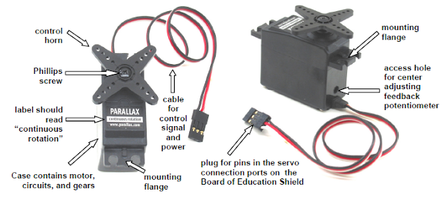
A Servo motor is a small device that incorporates a three wire DC motor, a gear train, a potentiometer, an integrated circuit, and an output shaft bearing. Of the three wires that stick out from the motor casing, one is for power, one is for ground, and one is a control input line. The shaft of the servo can be positioned to specific angular positions by sending a coded signal. As long as the coded signal exists on the input line, the servo will maintain the angular position of the shaft. If the coded signal changes, then the angular position of the shaft changes.


Here is an image of a servo-motor:

This is a special kind of motor, often used as the "muscles" of a robot. A servomotor takes a stream of pulses, where the width of each pulse controls the absolute position of the servo. This allows for precise positioning of motor turns. To do this, we're going to use a 555 timer in "Astable" mode - this will run it as an oscillator.


Here is the circuit diagram used for controlling the servo motor:


The two switches controls the rotation of the servo. The circuit is powered by a 7V DC source.


Here are some images of our Robotic Arm [Gripper]:


The output of our gripper was not well-designed due to limitation of resources and time. But at least we pulled out something like this. All of the parts from the gripper are recycled parts as well as the servo motor. The servo motor was found in a garbage can, believe it or not. LOL (-_~)

Here is a unit test video of our Gripper:

Project Made By:
Kirk Benedict P. Macaraeg
Jonald B. Sarmiento
Lindsey Baguio

Wednesday 2 October 2013

SUMOBOT


This is basically our project on our mechatronics subject at NDDU. We were tasked to create a sumobot for the final semester. This was an awesome experience to have especially in designing and building a sumobot. It was very challenging to create such thing our from you imagination. So here are the steps of how I assembled my sumobot.

First step: CREATING THE SUMOBOT BUMPER

(Front View)

3D View

Bottom View

Side View

Pictures which are shown above are my dimensions for the bumper design for pushing other sumobot out from the battle arena.

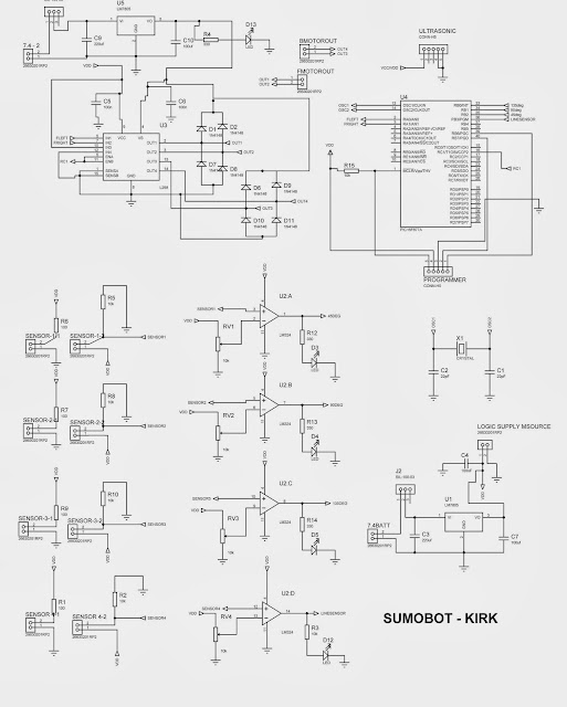
Second Step: CIRCUIT DESIGN

SUMOBOT CIRCUIT DESIGN

The image shown above is my personal circuit design. I utilized a PIC16F877A microcontroller. There were 4 CNY70 sensors that were implemented. 3 sensors for sensing the opponent and the other sensor for sensing the arena track in order for my sumobot to avoid in getting out of the arena. 

Program code:
#include <pic.h>
#include "delay.h"

__CONFIG(HS & WDTDIS & PWRTDIS & UNPROTECT & LVPDIS);

#define LeftCol RB0
#define BackCol RB1
#define RightCol RB2
#define FrontLine RB3
#define Forward 0x05
#define Left 0x06
#define Right 0x09
#define Backward 0x0A
#define Stop 0x00
#define Full 0b11111001
#define Reduce 0b11000111


void PWMInit(void);

void main()
{
TRISB=0xFF;
TRISA=0x00;
PORTB=0x00;
ADCON1=0x06;
PWMInit();
capture_init();
TRISC=0x00;
RC1=1;

while(1)
{

if(FrontLine==1)
{
if(LeftCol==1)
{
PORTA=Left;CCPR2L=Full;
}
else if(RightCol==1)
{
PORTA=Right;CCPR2L=Full;
}
else if(BackCol==1)
{
PORTA=Backward;CCPR2L=Full;
}
else if(LeftCol==0 && RightCol==0 && BackCol==0)
{
PORTA=Forward;CCPR2L=Full;
}
}
else if(FrontLine==0)
{

PORTA=Backward;
DelayMs(250);
DelayMs(250);
PORTA=Stop;
DelayMs(250);
PORTA=Right;
DelayMs(250);
DelayMs(250);
DelayMs(250);
PORTA=Stop;
DelayMs(250);
PORTA=Forward;
DelayMs(250);
DelayMs(250);
}
}
}

//Initialize CCP1 & CCP2 for PWM Operation
void PWMInit(void)
{
TMR2 = 0x00; //Clear TMR2 & CPP related registers
T2CON = 0x00;
CCP2CON = 0x00;
PR2 = 249; //Set PWM freq = 5Khz
CCPR2L = Full; //Set PWM2 Duty Cycle
TRISC2 =0; //Enable PWM1 output pin
TRISC1 = 0; //Enable PWM2 output pin
T2CKPS1 = 0; //Prescaler = 4
T2CKPS0 = 1;
CCP1CON-0x0C; //CCP1 in PWM mode
CCP2CON = 0x0C; //CCP2 in PWM mode
TMR2ON = 1; //Enable TMR2. PWM signal is generated.
return;
}

Third Step: TESTING & TROUBLESHOOTING

Well, as an electronics engineering student, one of the most challenging and fun thing to do is testing the unit and troubleshooting if there may seem to be no full functionality of the unit. Troubleshooting enhances one's skill in order to accomplish the desired goal. It may seem tiring but the accomplishment is worth striving for. So never give up if you may have messed up in creating you sumobot or if the result may not be fully functional, because as an ECE, we should be patient and persistent in troubleshooting things. =)


HERE ARE SOME IMAGES OF MY SUMOBOT:


Here is the sample vid


THE RESULT?
I won with my SUMOBOT for the Championship!..  =)

Wednesday 23 January 2013

MOBOT (Line Follower Robot)

One of the most exciting engineering projects that has been implemented here at NDDU is the MOBOT. Mobot is basically a line follower robot or also known as a mobile robot that follows a certain path by sensing the track. Students at NDDU competes for the fastest and accurate line follower robot. A race is annually held during the Engineering Exhibit and all engineering students under the microprocessor class are qualified to join this event. This event is one of the most top project controversy for the Engineering department. As for me, I am very excited in making this project and for the competition as well.

Shown below is the schematic diagram of the MOBOT:


Parts Used:

LM324 - operational amplifiers
L298 - H-Bridge (IC)
CNY70 - optocoupler sensors
PIC16f877a - microprocessor
Trimmer/potentiometer - adjustable resistor
LM7805 or LM323 or any regulators that has 3A rating and adjust the voltage to 5V.
(I suggest to use LM323 because it has a 3A current rating)
resistors, capacitors
crystal oscillator- 20MHz
header pins
wires
RC Car

Program Code:

// HARDWARE:
// - PIC16F877A, 20MHz High Speed Oscillator
// - Oscillscope probe --> RC2/CCP1 (PWM1)
// - Oscillscope probe --> RC1/CCP2 (PWM2)

/*


*/


#include <pic.h>
#include "delay.h"

//SENSOR

//#define RIGHT RB0
//#define MIDDLE RB1
//#define LEFT RB2

#define RIGHT RB2
#define MIDDLE RB1
#define LEFT RB0
#define STOPPER RA2

//Configuration bits
__CONFIG(HS & WDTDIS & PWRTDIS & UNPROTECT & LVPDIS);


//Defines
#define normal 0b11000111 //PWM2 Duty Cycle = 90
#define slow 0b10101110 /*value here (PWM Duty Cycle = 80%)*/
#define slowest 0b10101110 /*value here (PWM Duty Cyle= 70%)*/


//Function Prototypes
void PWMInit(void);
unsigned int a=0;

void main()
{
TRISB = 0x0F;
TRISA = 0b00000100;
ADCON1 = 0x06;
PWMInit();

while(1)
{

if(RA2==1)
{
if(LEFT == 1 && MIDDLE == 0 && RIGHT == 1)
{
RA0 = 0;RA1 = 0;CCPR2L=normal;
}
else if(LEFT == 0 && MIDDLE == 0 && RIGHT == 1)
{
RA0 = 1;RA1 = 0;CCPR2L=slow;
}
else if(LEFT == 1 && MIDDLE == 0 && RIGHT == 0)
{
RA0 = 0;RA1 = 1;CCPR2L=slow;
}
else if(LEFT == 0 && MIDDLE == 1 && RIGHT == 1)
{
RA0 = 1;RA1 = 0;CCPR2L=slowest;
}
else if(LEFT == 1 && MIDDLE == 1 && RIGHT == 0)
{
RA0 = 0;RA1 = 1;CCPR2L=slowest;
}

}
else if(RA2==0)
{
CCPR2L=0;
}
}
}

/*----------------------------------------------------------------

PWM PROGRAMMING

----------------------------------------------------------------*/

//Initialize CCP1 & CCP2 for PWM Operation
void PWMInit(void)
{
TMR2 = 0x00; //Clear TMR2 & CPP related registers
T2CON = 0x00;
CCP1CON = 0x00;
CCP2CON = 0x00;
PR2 = 249; //Set PWM freq = 5Khz
CCPR2L = normal; //Set PWM2 Duty Cycle
TRISC1 = 0; //Enable PWM2 output pin
T2CKPS1 = 0; //Prescaler = 4
T2CKPS0 = 1;
CCP2CON = 0x0C; //CCP2 in PWM mode
TMR2ON = 1; //Enable TMR2. PWM signal is generated.
return;
}


For the micro-controller part, I used the PIC16F877A. I utilized this PIC due to the fact that I allocated its PWM pin in order to control the speed of my motor. It really takes time to have an accurate design and codes for this project. There are numerous ways to do this project and this is one of the easiest circuit I have seen. I actually used a CNY70 for the sensors. Based on the circuit given above, the sensor there is the CNY70. To determine the pins, be sure to have the mark point of the CNY70 on your right. 

Here is the output of my MOBOT:

Note: The design is basically up to you on how creative you are.  =)


MOBOT MADE BY:

KIRK BENEDICT P. MACARAEG

Security Alarm Using the SCR

Security Alarm is basically a proposal project for our Industrial Engineering subject. We were tasked to make a prototype project that involves the use of the SCR. The idea that me and my group came up with is the SCR, but with modification. Certainly of course, it is much more better if a circuit can be modified in order to enhance the previous one. What me and my group added on the circuit was an LCD and the use of a micro-controller which is a PIC16F877A.

This is basically the circuit we found on the internet.


And this was the modified circuit we made from the circuit above.


What happened here is that we added a PIC16F877A micro-controller to have an LCD display and a modification on the buzzer. Also, we added two switches on the SCR circuit in order to turn off the alarm if it turns on. Ideally, the alarm switch would be placed on a certain protected unit and the main switch is placed next to the user to turn off the alarm at any case. When the alarm is triggered, a signal would be sent to the PIC as my input. Once the PIC receives a signal from the input, the buzzer would alarm and there would be a displayed text appearing from the LCD display such as "Intruder Alert". The LCD display here is basically the J1. I am using the JHD162A 16 Char x 2 Lines Alphanumeric LCD Display. Once the alarm is switched off by the user, the buzzer stops and the display returns to its original state where in the text displayed is "Security Alarm Standby". This circuit is basically for security basis for houses, private rooms, banks, and etc. This is a very useful circuit in terms of prioritizing and securing a certain area.

Here is our final output of the project:


PROJECT MADE BY:

KIRK BENEDICT P. MACARAEG
KEEN LAUD
JUSTIN IDA CABANLIT
JEROME ALVAREZ
JESUS VICENTE BELONIO