Wednesday, 23 January 2013

MOBOT (Line Follower Robot)

One of the most exciting engineering projects that has been implemented here at NDDU is the MOBOT. Mobot is basically a line follower robot or also known as a mobile robot that follows a certain path by sensing the track. Students at NDDU competes for the fastest and accurate line follower robot. A race is annually held during the Engineering Exhibit and all engineering students under the microprocessor class are qualified to join this event. This event is one of the most top project controversy for the Engineering department. As for me, I am very excited in making this project and for the competition as well.

Shown below is the schematic diagram of the MOBOT:


Parts Used:

LM324 - operational amplifiers
L298 - H-Bridge (IC)
CNY70 - optocoupler sensors
PIC16f877a - microprocessor
Trimmer/potentiometer - adjustable resistor
LM7805 or LM323 or any regulators that has 3A rating and adjust the voltage to 5V.
(I suggest to use LM323 because it has a 3A current rating)
resistors, capacitors
crystal oscillator- 20MHz
header pins
wires
RC Car

Program Code:

// HARDWARE:
// - PIC16F877A, 20MHz High Speed Oscillator
// - Oscillscope probe --> RC2/CCP1 (PWM1)
// - Oscillscope probe --> RC1/CCP2 (PWM2)

/*


*/


#include <pic.h>
#include "delay.h"

//SENSOR

//#define RIGHT RB0
//#define MIDDLE RB1
//#define LEFT RB2

#define RIGHT RB2
#define MIDDLE RB1
#define LEFT RB0
#define STOPPER RA2

//Configuration bits
__CONFIG(HS & WDTDIS & PWRTDIS & UNPROTECT & LVPDIS);


//Defines
#define normal 0b11000111 //PWM2 Duty Cycle = 90
#define slow 0b10101110 /*value here (PWM Duty Cycle = 80%)*/
#define slowest 0b10101110 /*value here (PWM Duty Cyle= 70%)*/


//Function Prototypes
void PWMInit(void);
unsigned int a=0;

void main()
{
TRISB = 0x0F;
TRISA = 0b00000100;
ADCON1 = 0x06;
PWMInit();

while(1)
{

if(RA2==1)
{
if(LEFT == 1 && MIDDLE == 0 && RIGHT == 1)
{
RA0 = 0;RA1 = 0;CCPR2L=normal;
}
else if(LEFT == 0 && MIDDLE == 0 && RIGHT == 1)
{
RA0 = 1;RA1 = 0;CCPR2L=slow;
}
else if(LEFT == 1 && MIDDLE == 0 && RIGHT == 0)
{
RA0 = 0;RA1 = 1;CCPR2L=slow;
}
else if(LEFT == 0 && MIDDLE == 1 && RIGHT == 1)
{
RA0 = 1;RA1 = 0;CCPR2L=slowest;
}
else if(LEFT == 1 && MIDDLE == 1 && RIGHT == 0)
{
RA0 = 0;RA1 = 1;CCPR2L=slowest;
}

}
else if(RA2==0)
{
CCPR2L=0;
}
}
}

/*----------------------------------------------------------------

PWM PROGRAMMING

----------------------------------------------------------------*/

//Initialize CCP1 & CCP2 for PWM Operation
void PWMInit(void)
{
TMR2 = 0x00; //Clear TMR2 & CPP related registers
T2CON = 0x00;
CCP1CON = 0x00;
CCP2CON = 0x00;
PR2 = 249; //Set PWM freq = 5Khz
CCPR2L = normal; //Set PWM2 Duty Cycle
TRISC1 = 0; //Enable PWM2 output pin
T2CKPS1 = 0; //Prescaler = 4
T2CKPS0 = 1;
CCP2CON = 0x0C; //CCP2 in PWM mode
TMR2ON = 1; //Enable TMR2. PWM signal is generated.
return;
}


For the micro-controller part, I used the PIC16F877A. I utilized this PIC due to the fact that I allocated its PWM pin in order to control the speed of my motor. It really takes time to have an accurate design and codes for this project. There are numerous ways to do this project and this is one of the easiest circuit I have seen. I actually used a CNY70 for the sensors. Based on the circuit given above, the sensor there is the CNY70. To determine the pins, be sure to have the mark point of the CNY70 on your right. 

Here is the output of my MOBOT:

Note: The design is basically up to you on how creative you are.  =)


MOBOT MADE BY:

KIRK BENEDICT P. MACARAEG

Security Alarm Using the SCR

Security Alarm is basically a proposal project for our Industrial Engineering subject. We were tasked to make a prototype project that involves the use of the SCR. The idea that me and my group came up with is the SCR, but with modification. Certainly of course, it is much more better if a circuit can be modified in order to enhance the previous one. What me and my group added on the circuit was an LCD and the use of a micro-controller which is a PIC16F877A.

This is basically the circuit we found on the internet.


And this was the modified circuit we made from the circuit above.


What happened here is that we added a PIC16F877A micro-controller to have an LCD display and a modification on the buzzer. Also, we added two switches on the SCR circuit in order to turn off the alarm if it turns on. Ideally, the alarm switch would be placed on a certain protected unit and the main switch is placed next to the user to turn off the alarm at any case. When the alarm is triggered, a signal would be sent to the PIC as my input. Once the PIC receives a signal from the input, the buzzer would alarm and there would be a displayed text appearing from the LCD display such as "Intruder Alert". The LCD display here is basically the J1. I am using the JHD162A 16 Char x 2 Lines Alphanumeric LCD Display. Once the alarm is switched off by the user, the buzzer stops and the display returns to its original state where in the text displayed is "Security Alarm Standby". This circuit is basically for security basis for houses, private rooms, banks, and etc. This is a very useful circuit in terms of prioritizing and securing a certain area.

Here is our final output of the project:


PROJECT MADE BY:

KIRK BENEDICT P. MACARAEG
KEEN LAUD
JUSTIN IDA CABANLIT
JEROME ALVAREZ
JESUS VICENTE BELONIO

FM (Frequency Modulator) & AM (Amplitude Modulation) Transmitter

On our Electronics Communication subject, our project was to create both FM and AM transmitter. The FM (Frequency Modulation) transmitter plugs into the audio output of audio devices and converts the audio output into an FM radio signal, which can then be picked up by appliances such as car or portable radios. It is called as an FM Transmitter due to the fact that we are dealing with the frequency modulation. An AM (Amplitude Modulation)  is a technique used in electronic communication, most commonly for transmitting information via a radio carrier wave. AM works by varying the strength of the transmitted signal in relation to the information being sent. For example, changes in signal strength may be used to specify the sounds to be reproduced by a loudspeaker, or the light intensity of television pixels.

Here is the schematic diagram for the FM Transmitter:

The value of the inductor used in this circuit is basically 200uH. The inductors value changes the frequency range. You may change the value of the inductor by using the frequency formula shown below:


As for the AM (Amplitude Modulation), here is the schematic diagram:


Here are some pictures of my Transmitters:
(This is only the AM Transmitter. I wasn't able to take a picture of my FM Transmitter. So sorry for that.)


PROJECT MADE BY:
KIRK BENEDICT P. MACARAEG

Amplifier Project - DOMO

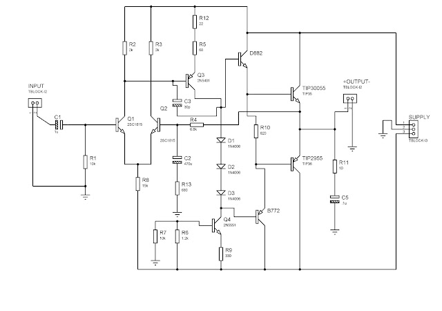
On our Electronics 2 subject, we mostly tackled about the amplification of a signal from the different types of transistors. A Transistor is an semiconductor which is a fundamental component in almost all electronic devices. Transistors are often said to be the most significant invention of the 20th Century. Transistors have many uses including switching, voltage/current regulation, and amplification - all of which are useful in renewable energy applications. A transistor controls a large electrical output signal with changes to a small input signal. This is analogous to the small amount of effort required to open a tap to release a large flow of water. Since a large amount of current can be controlled by a small amount of current, a transistor acts as an amplifier. Our project regarding about this subject was to create an amplifier design depending on how much power we desire for our amplifier with the use of transistors ONLY.

This is the schematic diagram of our amplifier:


This is basically a 40 W power amplifier.

NOTE:

SUPPLY:
The supply used for this is +24V and -24V 3A center tapped transformer. Then, the the transformer goes through a rectifier bridge which will convert the AC voltage of -24V and +24V to obtain a DC voltage of -35 V and +35 V output for the main circuit supply. A circuit is shown below for obtaining the 35V and -35V.

CAPACITOR V-Rating:
Also the capacitor voltage needed is 50V. It is normally recommended to give a good amount of room when choosing the voltage of the capacitor. Meaning, if you want a capacitor to hold 35 volts, don't choose exactly a 35 volt-rated capacitor. Leave some room for a safety margin just in case the power supply voltage ever increase due to any reasons in order to avoid explosion of the capacitor as it charges.

RESISTOR Wattage-Rating:
An ideal wattage of a resistor to be used for this circuit is a 1/2 or 1 watt resistor. The purpose of this is to emulate a pure resistance in a circuit and to avoid the resistor from burning up due to heat by resisting the current in a large amount of power.

COMMON GROUND:
Ensure your circuit to have all the grounds to be common, from AC to DC connections. All of the ground connection must be connected together to avoid "humming" sound from the speaker. A system grounded at two different points with a potential difference between the two grounds can cause unwanted noise voltage in the circuit paths. BE SURE TO CONNECT ALL GROUNDS INTO A SINGLE POINT GROUND.

HEAT SINK:
As for the transistors such as the "TIP3055"(i misspelled the number on the circuit) and the "TIP2955" it would need a huge heat sink since this two transistors are responsible form the amplification of the signal, therefore dissipating a lot of heat. As you can see on the images below in the inside of the case, there are two long metal rods place on the side, those are the heat sink for our transistors since it emits larger power amplification thus dissipating a lot of heat.


This is the schematic diagram of the power supply used in this Amplifier. Credits to Engr. Kendrick Villaruel and Engr. Ella Laguindam for providing this circuit.


In order to clearly understand and comprehend how the set-up works, here is a picture of how the amplifier is being assembled.


What happened in this diagram???

Well first of all, we bought a pre-amplifier from an electronics shop. The pre-amp is a ready made circuit in which it would be connected to the main amplifier circuit in order to perform an amplification from our amplifier. To make it short, the sounds from the pre-amp would be amplified by the main amplifier circuit. The pre-amp I bought was a 20 W amplifier. The 20 W will be amplified by the 40 W circuit to maximize the power from the main circuit. Then from the main amplifier, it directly goes out to the speakers and the tweeters. Be sure to check the specification of the component needed for this circuit.

NOTE:

TWEETER:
As for the tweeter, you would need a non-polarized capacitor with a value of 2.2uF/50V or higher, also known as capacitor "condenser". The capacitor in this circuit acts as a high pass filter, which means it will block low frequency component and let the high frequency component pass through. It will attenuate the low frequency.

12Volts:
You might wonder why there is a regulated 12VDC or an unregulated 12VDC located on the circuit. The 12VDC is used to power up the pre-amp. You can choose between the two either you make your own 12VDC or just purchase an adapter from an electronic shop with an ampere rating of 1.5A. But if you're transformer is 3A, it is much better to generate your own 12VDC for supplying the pre-amp.

Here are some pictures of the 40W amplifier construction. 


Our casing design was made to be DOMO. DOMO was a famous cartoon character from our school during that time, so me and my partner decided to have our amplifier case to be DOMO. It was fun and exhausting making this amplifier. Fortunately, we were able to finish it up and showed off our amplifier during the engineering exhibit.

Here are some videos from our DOMO Amplifier.

Inside DOMO


Engineering Exhibit (DOMO)


DOMO AMPLIFIER MADE BY:

KIRK BENEDICT P. MACARAEG & JONALD B. SARMIENTO

Regulated Power Supply

During our 3rd Year at NDDU, we were tasked to create our own variable regulated power supply. As we all know, A power supply is a device that takes an incoming electrical current and amplifies it to levels required by various devices. In many instances, a power supply is also implemented to take the incoming electricity and deliver it across many other electronic devices, often at different preset levels. This project was very shocking at first for we were dealing with AC to DC conversion (step down) power supply and we all know how dangerous AC could be. It was tricky and fun to think how it should be done and handled, but at the end, my group was able t perform and complete the project. We experienced various effects during the test for some reasons. Pictures and schematic diagrams are shown below on how we created our power supply. 


Materials used in making the power supply:

*Transformer, 24V, 2A
* Resistors: 18k and 220 ohms
*Potentiometer, 5k ohms
*Capacitors: 2200uF, 0.1uF, and 1uF
*Plug
*Diode – 1N4001
*Bridge Rectifier
*Heat Sink
*Transistor – LM317
*Printed Circuited Board
*Ferric Chloride
*Masking Tape
*Drill
*Soldering Iron
*Multitester
*Banana Jacks
*LED

Schematic Diagram :


The schematic shown at the top is basically the Regulated Power Supply that we created for our project in Electronics 1.

Note: Be sure to have a transformer with an ampere rating of at least 1.5 A and above. As what I have mentioned earlier, we experienced one problem that was a nuisance in our troubleshooting. That is because, when we created this project  the Ampere rating that we have for our transformer was only 1 A, along with this, when you place a load a huge load, there would be a huge drop on your voltage Why??The answer to this is based on the LM317. The specification on its datasheet is that you must at least have a 1.5 A current rating in order to have this properly worked out. If not, you would experience a huge drop when you would place a load for this supply.

This is our variable regulated power supply output:


CREATED BY:
KIRK BENEDICT P. MACARAEG
JONALD B. SARMIENTO
LEO PATRICK PANTI