Friday, 11 October 2013

Robotic Arm (Gripper) [Using servo motor with 555 timer]

One of the requirements for the 1st semester in our Robotics subject is to create a robotic arm or either a gripper. Our group decided to create a robotic arm but we didn't have enough time and resources to create a robotic arm, instead we made a gripper/end-effector. Our gripper is controlled by a servo motor. The servo motor is driven by a 555 timer. We connected two tact-switch for the gripping functionality of the gripper.

So what is a servo motor and how was it controlled by the 555 timer?


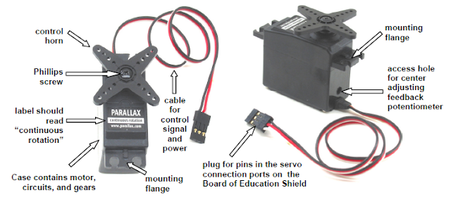
A Servo motor is a small device that incorporates a three wire DC motor, a gear train, a potentiometer, an integrated circuit, and an output shaft bearing. Of the three wires that stick out from the motor casing, one is for power, one is for ground, and one is a control input line. The shaft of the servo can be positioned to specific angular positions by sending a coded signal. As long as the coded signal exists on the input line, the servo will maintain the angular position of the shaft. If the coded signal changes, then the angular position of the shaft changes.


Here is an image of a servo-motor:

This is a special kind of motor, often used as the "muscles" of a robot. A servomotor takes a stream of pulses, where the width of each pulse controls the absolute position of the servo. This allows for precise positioning of motor turns. To do this, we're going to use a 555 timer in "Astable" mode - this will run it as an oscillator.


Here is the circuit diagram used for controlling the servo motor:


The two switches controls the rotation of the servo. The circuit is powered by a 7V DC source.


Here are some images of our Robotic Arm [Gripper]:


The output of our gripper was not well-designed due to limitation of resources and time. But at least we pulled out something like this. All of the parts from the gripper are recycled parts as well as the servo motor. The servo motor was found in a garbage can, believe it or not. LOL (-_~)

Here is a unit test video of our Gripper:

Project Made By:
Kirk Benedict P. Macaraeg
Jonald B. Sarmiento
Lindsey Baguio
Wednesday, 2 October 2013

SUMOBOT


This is basically our project on our mechatronics subject at NDDU. We were tasked to create a sumobot for the final semester. This was an awesome experience to have especially in designing and building a sumobot. It was very challenging to create such thing our from you imagination. So here are the steps of how I assembled my sumobot.

First step: CREATING THE SUMOBOT BUMPER

(Front View)

3D View

Bottom View

Side View

Pictures which are shown above are my dimensions for the bumper design for pushing other sumobot out from the battle arena.

Second Step: CIRCUIT DESIGN

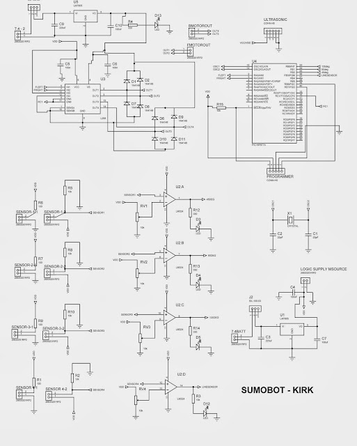
SUMOBOT CIRCUIT DESIGN

The image shown above is my personal circuit design. I utilized a PIC16F877A microcontroller. There were 4 CNY70 sensors that were implemented. 3 sensors for sensing the opponent and the other sensor for sensing the arena track in order for my sumobot to avoid in getting out of the arena. 

Program code:
#include <pic.h>
#include "delay.h"

__CONFIG(HS & WDTDIS & PWRTDIS & UNPROTECT & LVPDIS);

#define LeftCol RB0
#define BackCol RB1
#define RightCol RB2
#define FrontLine RB3
#define Forward 0x05
#define Left 0x06
#define Right 0x09
#define Backward 0x0A
#define Stop 0x00
#define Full 0b11111001
#define Reduce 0b11000111


void PWMInit(void);

void main()
{
TRISB=0xFF;
TRISA=0x00;
PORTB=0x00;
ADCON1=0x06;
PWMInit();
capture_init();
TRISC=0x00;
RC1=1;

while(1)
{

if(FrontLine==1)
{
if(LeftCol==1)
{
PORTA=Left;CCPR2L=Full;
}
else if(RightCol==1)
{
PORTA=Right;CCPR2L=Full;
}
else if(BackCol==1)
{
PORTA=Backward;CCPR2L=Full;
}
else if(LeftCol==0 && RightCol==0 && BackCol==0)
{
PORTA=Forward;CCPR2L=Full;
}
}
else if(FrontLine==0)
{

PORTA=Backward;
DelayMs(250);
DelayMs(250);
PORTA=Stop;
DelayMs(250);
PORTA=Right;
DelayMs(250);
DelayMs(250);
DelayMs(250);
PORTA=Stop;
DelayMs(250);
PORTA=Forward;
DelayMs(250);
DelayMs(250);
}
}
}

//Initialize CCP1 & CCP2 for PWM Operation
void PWMInit(void)
{
TMR2 = 0x00; //Clear TMR2 & CPP related registers
T2CON = 0x00;
CCP2CON = 0x00;
PR2 = 249; //Set PWM freq = 5Khz
CCPR2L = Full; //Set PWM2 Duty Cycle
TRISC2 =0; //Enable PWM1 output pin
TRISC1 = 0; //Enable PWM2 output pin
T2CKPS1 = 0; //Prescaler = 4
T2CKPS0 = 1;
CCP1CON-0x0C; //CCP1 in PWM mode
CCP2CON = 0x0C; //CCP2 in PWM mode
TMR2ON = 1; //Enable TMR2. PWM signal is generated.
return;
}

Third Step: TESTING & TROUBLESHOOTING

Well, as an electronics engineering student, one of the most challenging and fun thing to do is testing the unit and troubleshooting if there may seem to be no full functionality of the unit. Troubleshooting enhances one's skill in order to accomplish the desired goal. It may seem tiring but the accomplishment is worth striving for. So never give up if you may have messed up in creating you sumobot or if the result may not be fully functional, because as an ECE, we should be patient and persistent in troubleshooting things. =)


HERE ARE SOME IMAGES OF MY SUMOBOT:


Here is the sample vid


THE RESULT?
I won with my SUMOBOT for the Championship!..  =)